
Physics lab manuals are crucial for verifying concepts, offering hands-on experience, and mastering product functions – a comprehensive guide for students and engineers alike!
Purpose of a Physics Lab Manual
The core purpose of a physics lab manual extends beyond simply providing instructions; it’s about fostering a deeper understanding of theoretical concepts through practical application. These manuals aim to arm students with hands-on experience, enabling them to verify established principles and explore the intricacies of matter and energy.
A well-structured manual serves as a guide, outlining experiments, activities, projects, and demonstrations designed to solidify learning. It bridges the gap between classroom theory and real-world phenomena, encouraging critical thinking and problem-solving skills. Furthermore, manuals often prepare students for college-level physics or immediate application in everyday life, offering a comprehensive learning experience. They are designed to help master the functions and capabilities of the product.
Importance of Practical Work in Physics
Practical work in physics is fundamentally important because it transforms abstract theories into tangible realities. It’s not merely about confirming existing principles, but about developing crucial skills like observation, data analysis, and error assessment. Hands-on experience allows students to engage with the scientific method directly, fostering a deeper, more intuitive grasp of physics concepts.
These experiences cultivate critical thinking and problem-solving abilities, preparing students for both academic pursuits and real-world applications. A lab manual facilitates this process, providing structured experiments and guidance. It encourages independent thought and allows for exploration beyond textbook examples, ultimately solidifying understanding and building confidence in scientific inquiry. It arms students with experience.

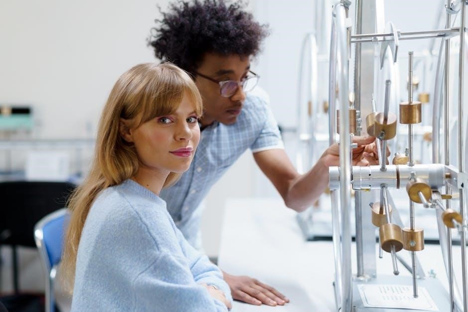
Essential Lab Equipment
Physics labs require precise tools – measuring and electrical instruments – to conduct experiments effectively, ensuring accurate data collection and reliable results for analysis.
Measuring Instruments
Measuring instruments are foundational to any physics laboratory, enabling precise determination of physical quantities. Accurate measurements are paramount for verifying theoretical principles and drawing valid conclusions from experiments. These tools extend beyond simple rulers; they encompass devices designed for high precision and specialized applications.
The selection of appropriate measuring instruments depends heavily on the experiment’s requirements, considering factors like the magnitude of the quantity being measured and the desired level of accuracy. Careful calibration and proper usage are essential to minimize errors and ensure reliable data. Understanding the limitations of each instrument is equally important for interpreting results correctly.
Common examples include rulers for length, balances for mass, and thermometers for temperature. However, more sophisticated instruments like vernier calipers and screw gauges offer significantly enhanced precision for measuring dimensions, while stopwatches and timers are crucial for kinematic studies. The proper handling and maintenance of these instruments are vital for their longevity and continued accuracy.
Vernier Calipers
Vernier calipers are precision instruments used to measure internal and external lengths, as well as depths, with greater accuracy than a standard ruler. They achieve this through a main scale and a vernier scale, which allows for readings to the nearest 0.02mm or 0.05mm, depending on the instrument. Understanding the vernier scale’s construction is key to accurate measurement; it’s a smaller auxiliary scale that slides along the main scale.
Proper usage involves zero error checking – ensuring the calipers read zero when jaws are fully closed – and careful alignment with the object being measured. Avoiding parallax error, by viewing the scale perpendicularly, is also crucial. Regular calibration against a known standard ensures continued accuracy. These instruments are invaluable for experiments requiring precise dimensional analysis.
Mastering vernier calipers is a fundamental skill in any physics laboratory, providing a foundation for more advanced measurement techniques and data analysis.

Screw Gauge
The screw gauge, also known as a micrometer screw gauge, is a precision instrument designed for measuring very small thicknesses, diameters, and depths with high accuracy – typically to 0.01mm. It operates on the principle of converting rotational motion into linear displacement using a precisely machined screw. The instrument features a thimble with a circular scale, which rotates relative to a fixed sleeve marked with a linear scale.
Accurate readings require understanding the pitch of the screw (distance moved per rotation) and the least count of the instrument. Similar to vernier calipers, checking for zero error and avoiding parallax are vital. Careful application of pressure is needed to obtain reliable measurements without deforming the object.
Screw gauges are essential for experiments involving thin wires, sheet thicknesses, and other small dimensions.
Electrical Instruments
Electrical instruments are fundamental to physics experiments exploring circuits, resistance, voltage, and current. A multimeter is a versatile tool capable of measuring these electrical quantities, functioning as an ammeter, voltmeter, and ohmmeter. Understanding its range settings and proper connection to circuits is crucial for accurate readings and preventing damage to the instrument or the circuit.
A power supply provides a stable source of voltage and current, essential for powering circuits under investigation. It allows for controlled variation of voltage and current levels, enabling systematic study of electrical behavior. Safe operation requires awareness of voltage and current limits.
Proper handling and calibration of these instruments are vital for reliable experimental results.
Multimeter
The multimeter stands as a cornerstone electrical instrument in any physics laboratory, serving as a versatile tool for measuring voltage, current, and resistance. It’s essentially three instruments in one: a voltmeter, ammeter, and ohmmeter. Before use, always verify the selected range is appropriate for the expected measurement to avoid damaging the device or obtaining inaccurate results.
Correct connection of the probes – red for positive, black for negative – is paramount. When measuring current, the multimeter must be connected in series with the circuit, while voltage measurements require parallel connection. Resistance measurements demand the circuit be de-energized.
Understanding these principles ensures safe and accurate data acquisition.
Power Supply
A power supply is an essential component in a physics lab, providing a stable and controlled source of electrical energy for experiments. These devices convert AC voltage from the mains to a regulated DC voltage, often adjustable within a specified range. It’s crucial to select a power supply with appropriate voltage and current ratings for the circuit being powered, preventing damage to components.
Always begin with the voltage set to its minimum value before switching on the power supply. Gradually increase the voltage to the desired level, monitoring the current draw to ensure it remains within safe limits.
Proper grounding and adherence to safety protocols are vital when working with power supplies.
Basic Physics Experiments ー Mechanics
Mechanics experiments, like length/volume measurements and motion studies, verify principles and laws, providing practical application of theoretical physics concepts.
Measurement of Length and Volume
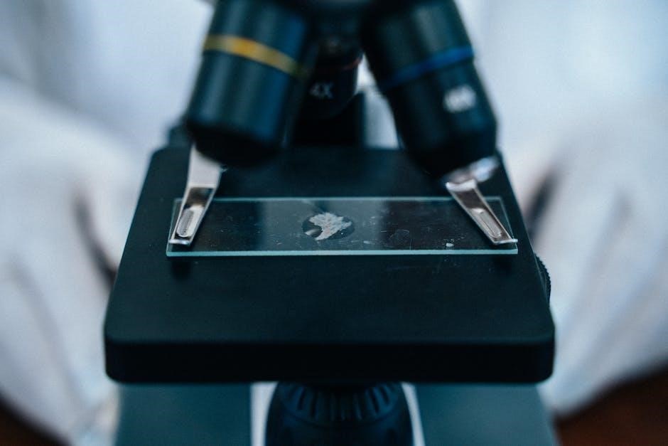
Accurate measurement forms the bedrock of experimental physics. This experiment focuses on mastering techniques for determining length and volume, utilizing instruments like rulers, vernier calipers, and measuring cylinders. Students will learn to measure the thickness of a glass plate, a fundamental skill in many physics applications.
The procedure involves repeated measurements to minimize random errors and careful observation to avoid parallax errors. Volume determination extends to both regular and irregular shaped objects, employing methods like displacement.
Data recording must be precise, including units and estimated uncertainties. Analyzing these measurements allows students to understand the concept of significant figures and propagate errors. This foundational experiment builds essential skills for more complex investigations in mechanics and beyond, emphasizing precision and methodical approach.
Study of Motion — Kinematics
Kinematics, the study of motion without considering its causes, is central to physics. This lab explores describing motion using concepts like displacement, velocity, and acceleration. Experiments typically involve analyzing the motion of objects – carts, balls, or pendulums – using techniques like ticker-tape timing or motion sensors.
Students will learn to graphically represent motion, interpreting position-time and velocity-time graphs to determine kinematic quantities. Calculating instantaneous and average velocities, alongside acceleration, are key objectives.
Emphasis is placed on understanding the relationship between these variables and applying kinematic equations to solve problems. Careful data collection and analysis, including error assessment, are crucial for validating theoretical predictions and developing a strong understanding of motion principles.
Measuring Velocity and Acceleration
Measuring velocity and acceleration forms a cornerstone of kinematic studies within the physics lab. Experiments often utilize motion sensors connected to data acquisition systems, providing precise position-time data. Students analyze this data to calculate instantaneous and average velocities, understanding the difference between scalar speed and vector velocity.
Acceleration is determined by examining the slope of velocity-time graphs, or by applying kinematic equations derived from constant acceleration scenarios. Techniques like using photogates and timers to measure time intervals over fixed distances are also common.
Error analysis is vital, considering uncertainties in time measurements and position readings. Graphical representation and data fitting help visualize and quantify these kinematic properties, reinforcing theoretical concepts with practical application.
Newton’s Laws of Motion
Newton’s Laws of Motion are fundamental to classical mechanics, and laboratory experiments provide a practical understanding of these principles. Labs typically involve applying forces to objects and observing the resulting motion, verifying the relationships between force, mass, and acceleration.
Students often use force sensors, spring balances, and dynamics carts to quantify forces and measure accelerations. Analyzing free-body diagrams is crucial for identifying all forces acting on an object. Experiments explore concepts like inertia, momentum, and the effects of friction.
Understanding these laws is essential for predicting and explaining the motion of objects in various scenarios, solidifying theoretical knowledge through hands-on investigation and data analysis.
Verification of Newton’s Second Law
Verification of Newton’s Second Law (F=ma) is a cornerstone experiment in physics labs. Typically, this involves applying a known force to an object of measured mass and then accurately determining the resulting acceleration. Students often utilize a dynamics cart on a low-friction track, employing weights and pulleys to provide controlled forces.
Acceleration is commonly measured using motion sensors or photogates; Data is then collected and analyzed to demonstrate the linear relationship between force and acceleration for a constant mass. Graphical representation of the data—force versus acceleration—should yield a straight line, with the slope representing the mass.
Careful consideration of uncertainties and error analysis is vital for a robust verification of this fundamental law.
Basic Physics Experiments ー Optics
Optics experiments within a physics lab manual explore light’s behavior, including reflection, refraction, lens formation, and focal length measurements for comprehensive understanding.
Reflection and Refraction of Light
This experiment delves into the fundamental principles governing how light interacts with different mediums. Students will meticulously measure the angle of incidence and the corresponding angle of refraction as a light ray transitions from one medium to another, typically from air to glass or water.
The core objective is to verify Snell’s Law, a cornerstone of optics, which mathematically defines the relationship between these angles and the refractive indices of the involved materials. Precise measurements are paramount, utilizing protractors and light sources carefully aligned on optical benches.
Understanding these concepts is vital for comprehending phenomena like the apparent bending of objects in water, the functioning of lenses, and the principles behind optical instruments. Careful observation and accurate data recording are essential for a successful and insightful laboratory experience, solidifying theoretical knowledge with practical application.
Measuring the Angle of Incidence and Refraction
This procedure requires a precise setup involving a light source, a semi-circular glass block, a protractor, and a sheet of paper. The light ray is directed towards the flat surface of the glass block, and the point of incidence is carefully marked on the paper.
Using the protractor, the angle of incidence – the angle between the incident ray and the normal (a line perpendicular to the surface) – is accurately measured. The refracted ray, the light’s path after entering the glass, is then traced, and its angle of refraction is similarly determined.
Multiple readings at varying angles are crucial for minimizing errors and establishing a reliable relationship. Students must ensure proper alignment and account for parallax errors during measurement. Detailed recording of observations in a tabular format is essential for subsequent analysis and verification of Snell’s Law.
Lens and Image Formation
This experiment explores the fundamental principles of how lenses converge or diverge light rays to form images. Utilizing a convex lens, an illuminated object (like a candle or a bulb), and a screen, students investigate the relationship between object distance, image distance, and magnification.
By systematically varying the object distance, the corresponding image distance is carefully measured. The characteristics of the image – whether real or virtual, inverted or erect, and magnified or diminished – are meticulously observed and recorded.
Precise measurements are vital for calculating the focal length of the convex lens, a key parameter defining its optical properties. Graphical analysis of the obtained data allows for the verification of the lens formula, solidifying understanding of image formation principles.
Focal Length of a Convex Lens
Determining the focal length of a convex lens is a cornerstone experiment in optics. This lab utilizes the lens formula – 1/f = 1/v, 1/u – where ‘f’ represents the focal length, ‘v’ the image distance, and ‘u’ the object distance. Students meticulously measure these distances for various object positions.
A key technique involves the distant object method, where the lens is adjusted to form a sharp image of a distant object on a screen; the distance between the lens and the screen approximates the focal length. Alternatively, the displacement method involves finding two lens positions that produce a sharp image for a single object distance.
Careful data recording and analysis, including graphical representation, are crucial for accurate focal length determination and verification of the lens formula’s validity. Error analysis helps assess the precision of the measurements.

Basic Physics Experiments, Electricity & Magnetism
Electricity and magnetism experiments, like Ohm’s Law verification and circuit analysis, provide practical insights into fundamental principles and their real-world applications.
Ohm’s Law Verification
Ohm’s Law, a cornerstone of electrical circuit theory, establishes the linear relationship between voltage (V), current (I), and resistance (R), expressed as V = IR. This experiment aims to empirically verify this fundamental law through practical measurements.
Typically, a circuit is constructed using a power supply, a resistor, an ammeter to measure current, and a voltmeter to measure voltage across the resistor. By systematically varying the voltage and recording the corresponding current, students gather data to analyze.
The collected data is then plotted on a graph with voltage on the x-axis and current on the y-axis. According to Ohm’s Law, this graph should yield a straight line passing through the origin. The slope of this line represents the resistance (R) of the resistor.
Precise measurements and careful observation of linearity are crucial for successful verification. Error analysis, considering instrument limitations and measurement uncertainties, is also an integral part of the experiment, ensuring a robust understanding of Ohm’s Law.
Series and Parallel Circuits
This experiment explores the fundamental differences in behavior between series and parallel circuits, crucial for understanding electrical network analysis. In a series circuit, components are connected end-to-end, forming a single path for current flow, while parallel circuits offer multiple paths.
Students construct both types of circuits using resistors, a power supply, and an ammeter to measure current and a voltmeter to measure voltage across each component. Measurements reveal that the current remains constant in a series circuit, but voltage divides across resistors.
Conversely, in a parallel circuit, voltage remains constant, while current divides among the branches. The experiment focuses on calculating the equivalent resistance for both configurations. For series, resistances add directly (Req = R1 + R2 + …), while for parallel, the reciprocal of the equivalent resistance equals the sum of the reciprocals of individual resistances (1/Req = 1/R1 + 1/R2 + …).
Verification of these calculations through practical measurements solidifies understanding of circuit behavior.
Calculating Resistance in Series and Parallel
A core component of the series and parallel circuits experiment involves precise resistance calculations. For series configurations, the total resistance (Req) is simply the algebraic sum of individual resistances: Req = R1 + R2 + R3… This straightforward addition reflects the single path for current, encountering each resistance sequentially.
However, parallel circuits demand a different approach. The reciprocal of the equivalent resistance equals the sum of the reciprocals of the individual resistances: 1/Req = 1/R1 + 1/R2 + 1/R3… This formula accounts for the multiple current paths, effectively reducing the overall resistance.
Students utilize Ohm’s Law (V = IR) and measured voltage and current values to independently determine experimental resistance values. Comparing these experimental values with those calculated theoretically using the formulas provides a crucial validation of the principles and highlights potential sources of error, such as component tolerances or measurement inaccuracies.
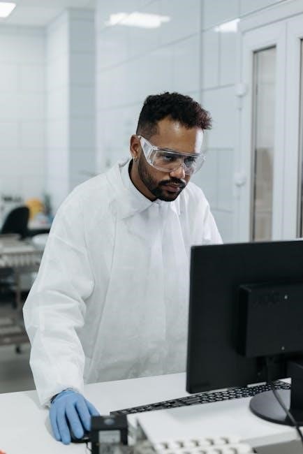
Data Analysis and Reporting
Physics lab reports demand meticulous observation recording, thorough error analysis, and insightful graphing for accurate interpretation of experimental results and principle validation.
Recording Observations
Precise and systematic recording of observations is paramount in any physics laboratory experiment. A well-maintained record serves as the foundation for accurate data analysis and reliable conclusions. Observations should be documented immediately, utilizing appropriately labeled tables with clear units.
Avoid ambiguity by noting down all relevant details, including instrument readings, environmental conditions, and any unexpected occurrences during the experiment. Raw data must be recorded before any calculations are performed, preserving the integrity of the original measurements.
Furthermore, employ significant figures correctly to reflect the precision of the measuring instruments. Detailed notes regarding the experimental setup and procedure are also essential for reproducibility and future reference. Consistent and organized observation recording is a hallmark of rigorous scientific practice.
Error Analysis
Accurate error analysis is a critical component of any physics experiment, acknowledging that perfect measurements are unattainable. Identifying and quantifying errors allows for a realistic assessment of experimental results and their associated uncertainties. Errors can be categorized as systematic, arising from instrument flaws or procedural biases, and random, stemming from unpredictable fluctuations.
Calculating percentage error, comparing experimental values to theoretical predictions, provides a quantitative measure of discrepancy. Propagation of errors, determining how uncertainties in individual measurements affect the final result, is also vital.
A thorough error analysis demonstrates a critical understanding of experimental limitations and enhances the validity of conclusions. Reporting all significant sources of error, alongside their estimated magnitudes, is essential for transparent and reproducible scientific work.
Graphing and Interpretation
Effective graphing is paramount for visualizing relationships between variables and interpreting experimental data within a physics lab. Choosing appropriate graph types – linear, logarithmic, or otherwise – depends on the expected relationship. Clearly labeling axes with variables and units, and selecting a suitable scale, are crucial for clarity.
Analyzing the graph’s slope, intercept, and shape reveals key physical parameters and confirms theoretical predictions. Determining the line of best fit, often using linear regression, minimizes the impact of random errors.
Interpreting the graph involves drawing meaningful conclusions about the underlying physics, considering potential sources of error, and comparing results to established theories. A well-presented graph, coupled with insightful interpretation, strengthens the validity of experimental findings.